Sunday, December 12, 2010

Product Design For the Inventor

Big business has streamlined this process but usually has whole departments dedicated to:
  • Product Design 
  • Product Development
  • Legal - Intellectual Property - Patent
  • Market Analysis
  • Prototype
  • Product Testing
  • Manufacturing
  • Packaging Design
  • Sales and Marketing 

Corporations and well established manufacturing companies have budgets and personal to make investments in new intellectual property and product development. But what about the inventor and or entrepreneur that doesn't work in an industry where these skills exist? And even if you do, your idea is yours.

As an experienced product engineer, I have seen too many products designs that on paper, are pretty to look at, but would be almost impossible to manufacture without expensive special tooling and/or a complete redesign. There is an amazing amount of difference between product design and product design for manufacturing. If the inventor intends on applying for a utility patent, they must also make certain that they have properly documented their invention and that the design professional signs a non-disclosure document before ideas are shared.

The entire product design process for the non-engineer. Topics covered will be:

  • Product Development and Idea Generation.
  • Idea Protection and Patent Considerations
  • Market Research
  • Product Liability
  • Hiring Design Professionals
  • Design For Manufacturing
  • Materials Selection
  • Prototyping
  • Packaging
  • Manufacturing Costs

Saturday, December 11, 2010

Steps For Successful Product Design

Developing a product can seem like a daunting task but if you know the basic steps and phases required things will be much easier. Product design can be broken into 7 steps that I will explain below.

Problem Assessment

It is a good idea to write down what the problem is first. Don't write down the solution to the problem at this point, even if you know how to do so. You simply need to state what the problem is and nothing more. I have seen the development of new products become complicated and time consuming simply because the problem was never written down. A proper statement of the problem helps keep everyone on the same page and works to eliminate project creep.

Design Specification

This is the step in which a solution to the previously defined problem begins to form. At this point a list of requirements of everything you can think of should be written down. You are not coming up with a solution just yet only setting the requirements necessary to create the product. Some examples of what should be on your list include, a retail price (how much are people whiling to pay for this), size of the object (does it need to fit into someone's hand or through a door or in a garage), how fast should it go, does it need to be water proof, what should it be made of, does it use batteries or plug into the wall. This list can go on and on but the important thing is that you list what is important to you. This list will help you and your designer in the next step.

Idea Generation

Now you are getting somewhere, the problem has been defined and requirements have been set. At this point you should brainstorm and sketch out your ideas. Don't worry if the drawings are not pretty, you are only trying to see if the concepts could work or if there is an obvious flaw. If you are not mechanically inclined, you may want to find someone who specializes in product or industrial design to help. Many design companies have no problem meeting with you to discuss and sketch a few ideas before you will be under any obligation to sign a contract or pay anything. You will want to come up with one or two good ideas before moving to the next step.

Concept Design

Once at least one good idea for the new product has been sketched you will want to have the design worked out in a little more detail. The designer will come up with a basic 3d design on a computer that is detailed enough to be sure the idea will work but not so detailed that it takes more than just a few hours to complete. This is the last step where an idea is either given the green light or trashed.

Detailed Design

Now that a solid concept design has been created its time to get down to the details. In this phase the designer will create full detail 3d virtual models of all parts, work out design problems, create assembly and part drawings for every part, find suppliers for all purchased components and create 3d physical prototypes if necessary. This phase is complete when all problems have been solved and a full set of drawings have been delivered.

Testing

Testing is a very important part of product design and should not be overlooked. This step can be as simple as having a few people use the product for feed back or as complicated as sending it to a testing laboratory such as UL for a thorough testing by professionals. The level of testing will most likely be determined by requirements of any retail stores that will be selling the product. It is important that you have someone test the product that has not been involved in the design process even if it's a friend. Someone who has not been part of the design will give a less biased opinion plus you can watch for any difficulty they may have using the product.

Manufacturing

The final step in the design process is manufacturing, in this step you or your designer will find suitable manufacturing facilities to create the product. You will need to come up with an agreement with the manufacturer on the terms of what they will be providing, the cost and when it will be delivered.

Bosses in Product Design

Bosses are small cylindrical elements in a design. They are used for accepting screws or other fastening components (threaded inserts usually). Essentially they are locating, mounting and assembly devices built in to the design of the part and if not for accepting screws, will attach to the mating part of another component of the design. To ensure the highest quality during the injection moulding of your part, there are design guidelines to follow when designing bosses.

  • Boss design elements:
    • Thickness ratio. Similarly to ribs, the wall thickness of bosses should be no more than 60 percent of the main wall thickness of the part.
    • Base radius ratio. The radius of the base should be at least 25 percent of the main wall thickness. Thus, the diameter of the base of the boss should be at least 50 percent.
    • Bosses should always be connected to adjacent walls using ribs or gussets. Often bosses are designed with thick wall parts or are connected to walls, resulting in a thick section of the part which can warp during manufacture.
    • The base of bosses, as with any attachment between two surfaces, should always be designed with a fillet ratio included. This will ensure that stresses experienced by the boss - such as through the insertion of a screw - will not result in fracture.

  • Boss failures and how to avoid them:
    • High hoop stresses. These are particularly annoying as they may only become apparent after the part is designed and the entire run has been injection moulded. High hoop stresses are caused when the insert damages the internal radius of the boss.
    • Knit lines. These lines appear when the flow of molten material is party cooled when it reaches the top of the boss. These lines are visible and can easily crack when pressure is applied. Knit lines can be controlled by moving the parting line of the mould. If this is not possible the addition of a gusset or rib is advised.
Bosses require careful thought when being designed. Due to their nature they are both one of the most fragile parts of the design and one of the elements in most need of strengthening.

Radius in Product Design

Definition:
1. A straight line extending from the center of a circle or sphere to the circumference or surface: The radius of  a circle is half the diameter. 

2. A rounded corner or edge on a machined, injection moulded or cast piece of metal or plastic.

The humble radius is an all-important factor of your product design, arguably as (or even more) important than the straight edge or plane. The radius must be calculated when designing for rounding corners, hole width, inside and outside wall radii, not to mention any curved plane. Every surface that is not dead straight will have been designed using a radius. Here is a run-down of radius use when designing your product to be sent for injection moulding.
  • Corners. Sharp corners are a bad idea in product design. Straight 90 degree angles can lead to a high concentration of stress in one small area (especially on the inside corner of an angled wall). It is very important to smooth out your corners using a consistent radius. The typically accepted formula holds that the outside radius should be 1.5 times the wall thickness and the inside should be 0.5 times the wall thickness. For instance, if your wall thickness is 6mm and you have two walls that meet at a 90 degree angle, your corners will need to be rounded. The outside radius will be 9mm, whilst the inside radius will be 3 mm.
  • Fillet radius. A fillet radius is a radius that smooths the connection between two parts, similar to the function of an inside radius for a corner. This has the same advantage - reducing stress - and may be complemented by a rib. A fillet radius may be used for attaching a boss to a plane or a rib to a wall. A fillet radius should be applied wherever two planes meet to create an angle, whether sharp or obtuse.
  • If your product design concept involves a curved plane of any kind, a radius should be applied to ensure a consistent and aesthetically pleasing design. In the same way that you would use a ruler to draw a straight line, you must use a radius to draw a curved line.
Applying radii to your design has many benefits. A radius allows the plastic to flow much more smoothly than a corner would. If a mould were to be created with sharp corners there is less of a guarantee that the entire mould would be filled, leaving gaps and a messy edge. A radius can handle stress a lot better than a corner or edge. An inside edge is nothing more than the starting place for a crack; it is where all the stress will be concentrated should your part be subjected to any amount of pressure, Finally and simply, rounded corners typically look better that sharp angles.

Autocad Exercise

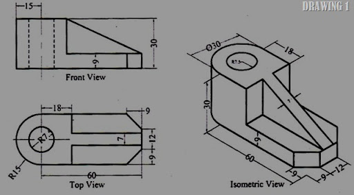
Orthographic Projection 1

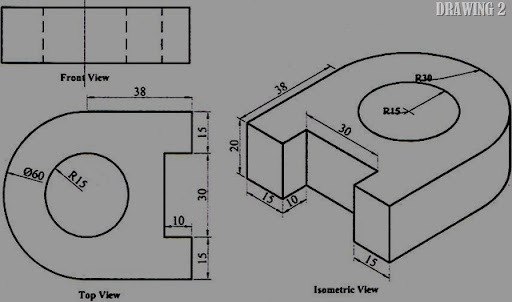
Orthographic Projection 2

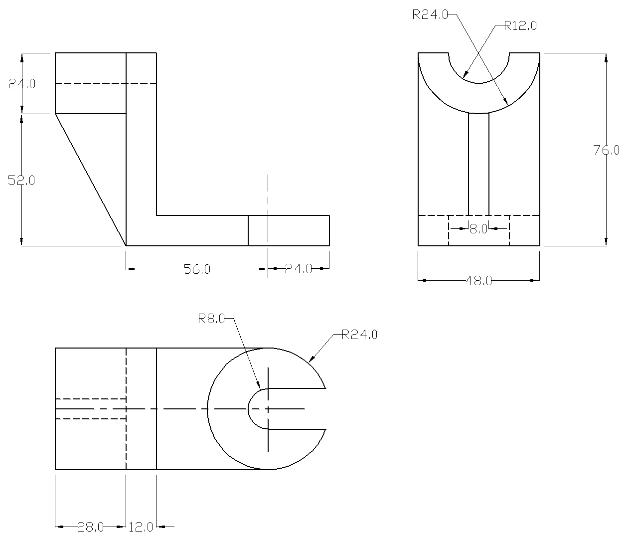
Orthographic Projection 3

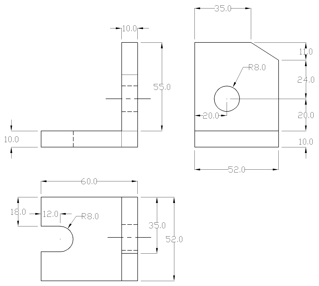
Orthographic Projection 4

Orthographic Projection 5

Orthographic Projection 6

Orthographic Projection 7

Orthographic Projection 8

Friday, December 10, 2010

Solidworks 3D CAD Design software: Better Product Design

The SolidWorks software suite offers superior capabilities that help the product/project manager to get to market faster - designers grab mistakes earlier, modify design quickly, take a right approach towards a problem and construct innovative products at much lower cost.

Whether you are a small or large company, the SolidWorks simulation software proves to be an efficient tool even in the most primitive product development stages. The major feature of this simulation technology is the opportunity that it provides to get answers related to the behavior of the products under different circumstances and operating conditions. The software provides design team right tools at the right time, to formulate 'what if' ideas part during the course of design life cycle. The outcome is Faster, Better and Cost-effective product design!

Major advantages of using SolidWorks 3D design simulation tool:


Complete focus on product design:
 
By making the 3D design process simple, SolidWorks can improve productivity of all users. Now there is no need to remember complex mathematical rules. The design team members can spend more time on creating better products and experiment with the design.

Easy testing: 
SolidWorks validation tools help you test your designs prior to the design life cycle under various criteria and real-time conditions. This facilitates superior design quality and production efficiency, thus reducing expenditures, time to market and materials wastage. In a brief survey, 66% of product designers acknowledged enhanced design quality using SolidWorks 3D design validation tools!

Improved communication, collaboration and access of data: With SolidWorks your team can share 3D models and act as a team with manufacturers and vendors to improve designs, maximize accuracy and enhance production efficiency.

A single platform for all: 
Sometimes it's a headache to operate over multiple applications to deliver a single job. It results in poor productivity and less innovation or creativity. SolidWorks allows users to work right from the product conceptualization to precision virtual prototyping over a single platform without ever opening another computer application.

Benefits of using AutoCAD for Mechanical Product Design & Drawings

AutoCAD Mechanical is a comprehensive Mechanical product design & drafting software catering to various needs of mechanical engineering companies. AutoCAD comes with a complete set of powerful drafting and detailing tools for drafting professionals - delivering the most efficient solutions in mechanical product design. Following mentioned some of the important functions and features of AutoCAD Mechanical design suite.

700,000 Standard Mechanical Components:

If you are working with machinery that requires hundreds or thousands of parts, it might take weeks or even months to draw them from scratch. Here AutoCAD Mechanical software can be of help to you. It has a comprehensive set of parts and features that you can choose for your designs. The software supports several manufactured parts such as Nuts, Screws, Washers, Rivets, Pins, Plugs, Bushings, Bearings, Structural Steel Shapes, Shaft Components, Key ways, Undercuts, Thread Ends and many more.

Powerful and Quick Dimensions:

With the use of simplified tools you can generate dimensions to easily control and expand only important variables for manufacturing. With automatic dimensioning, you can generate several dimensions with less input and force overlapping dimensions to automatically place themselves apart properly and even drive and adjust design geometry to fix in certain sizes.

Incorporation for International Drafting Standards:

AutoCAD supports BSI, ANSI, DIN, CSN, GB, ISO and GOST drafting platforms. Compliance with industry standards improve internal communication and results in reliable production outputs. The software comes with specific drafting tools for generating standards-based geometric dimensions, surface texture symbols, mechanical symbols and weld symbols. You can increase your productivity manifold and help your team deliver up-to-date, standards-based design documentation.

Automatic update across all drawings:

AutoCAD automatically redraw geometry to illustrate dashes and hidden lines of parts that are blocked by other parts in mechanical design. The hidden lines feature automatically update all relevant drawings when a change occur, practically removing lengthy manual redrawing of geometry due to repeat changes. This means you save time and efforts revising your 2D designs.

Easy Data Swapping over Different CAD Systems:

AutoCAD Mechanical suite comes with in-built industry-standard STEP (Standard for the Exchange of Product Data) and IGES (Initial Graphics Exchange Specification) formats for exchanging data between different CAD systems.

The Greatest Product Design Of All Time

When it comes to product design, there can be little doubt that plastic is the one time biggest invention that has helped make billions of items affordable and readily available to everybody.
Plastic, coming from the Greek word Plastikos meaning to mould or shape, is the product design of Alexander Parkes and was first publicly demonstrated at the 1862 Great International Exhibition in London. This is an organic material made from cellulose that can be heated and molded to any shape, retaining this new shape on cooling.

The invention of plastic has opened the doors to a myriad of new product designs that otherwise would either not have been possible, or at best would have still been invented but at vastly inflated prices as to those that plastic brings about.

Plastic has increasingly been used in product design throughout the years with varying popularity. Warehouses were full to the rafters with plastic furniture in the sixties but some people saw the products as 'cheap' as in cheap quality as well as cheap prices. And this was looked down upon for a time.


But that is the whole beauty of this product design. It is cheap. It is flexible, mouldable, resilient and very strong. It means that anything from furniture to food and drink containers, from toys to paints, from cameras and phones to radios - all have plastic elements.


Plastic can be colored in whatever way you want it to stand out or blend in, to look natural or completely manufactured.


The invention of plastic itself has opened doors to product design in every single area of life. And this itself brings about another problem. Plastic does not simply rot away. It can give off toxic fumes if burnt and will overwhelm landfill sites the world over.


However, there really is no reason to be throwing plastic items away in landfill sites as it can all be recycled. The problem arises in trying to encourage people to do the right thinking when plastic products are finished with. Water bottles are one derivative of plastic product design and with today's emphasis on health and well being many people have taken to constantly carrying water bottles with them and sipping regularly.


It seems crazy that they want a healthier body so they drink more water but care little about their environment to the point where they are quite happy to pollute it by not recycling in a responsible manner. In 2002, a staggering 15 billion plastic water bottles were produced and of this total, a mere 12 per cent were recycled. This compares with thirty per cent of soft juice drinks bottles but is still nowhere near enough.


It is relatively easy to recycle plastics and they can simply be reformed into something else. Take a look at the blonde woman from Texas. One minute she was normal but after some reforming with plastic surgery she turned into Pamela Anderson. All very well but what happens after death? In years to come will the ground be littered with plastic body parts that used to be implants?


On a more serious note, plastic surgery is one area that has hardly been touched by actual plastic and the name is slightly misleading. Plastic surgeons concentrate on remodeling bones, cartilage, muscle and skin using various products and are sometimes mistakenly called cosmetic surgeons.


One way or another, it has to be said that plastic is one of the greatest product design results the world has ever seen and has opened the floodgates for so many more possibilities. All we need to do is dispose of it responsibly and it will see us through many more generations.

PRODUCT DESIGN JOBS: Tips

Most people who watch a movie only see the actors and assume that where ever the film was shot was already in place. However; what they don't realize is that without exception the set was created to fit the needs of the production. The work is all done by production designers who specialize in creating the illusion of reality.


Production Design in it's Varied Forms


It can be anything from a coffee shop in New York to the interior of a space craft on a science fiction movie set, so a skilled production designer must be familiar with a wide range of materials and processes to use in production design.


Learning to Work With Others


Also, most people don't realize that production design is almost without acception, a collaborative effort. That is that if you are a production designer on a movie set you will be working with other production designers on the complete project. There is just too much work to be done and so little time to do it in for one person to take on the whole task.


Formal Training is a Necessity


The best place to get a real start in production design is in a production design academy. A good production design academy will teach you all the basics that you need and then actually take you through the steps of creating a variety of different movie sets.


Building a Track Record


This is important, because regardless of your natural skill level, you are going to have to have some documented prior experience before you can approach a legitimate production design company for employment. So, preparation is truly key to getting started with a career in production design.


Art Studies Can Only Help


However; until you are actually ready to start in with a private production design academy, there are a few things that you can do to hone your skills. Art classes at your local high school or community college are a great source of information and the things that you learn there you will carry with you into a formal production design academy.

SOLIDWORKS SIMULATION: How to use Simulation Software tools, to analyze and optimize product designs


To assess the performance of a variety of product designs in various domains many product manufacturers use analysis software to simulate. Analysis software enables designers to simulate design performance and identify and address potential design problems before prototyping and production.
Computer Aided Engineering (CAE) tools such as Finite Element Analysis (FEA), Computational Fluid Dynamics (CFD) and Motion Simulation as important aids to produce better designs faster over the years, because design engineers know that such tools help them design better products, that will withstand the toughest service and moreover CAD software's now comes with built-in FEA capabilities.
Design engineers who want to get best design and most profitable products while meeting the requirements for "worst case scenarios" to meet safety and strength standards may sometimes over design which can lead to increase in the cost of manufacturing, so the designer can take the advantage of CAE tool i.e. SolidWorks Simulation to meet the product functions in product development.
By using the Design Insight Plots and Trend Tracker options in SolidWorks Simulation, the design engineer will increase his knowledge of his product's behavior and improve upon the design, while adhering to the data obtained from previously completed analysis.

Design Insight Plot and Trend Tracker

A Design Insight plot shows the regions of the model that carry the loads most efficiently. This plot may be recognized as a "load path" plot and this information can be used to reduce the model's material. The model can be superimposed on a Design Insight plot while editing the geometry features.
Trend Tracker helps in evaluating the impact of successive design changes on the base design of a static study. Results are presented in a manner that compares a baseline to subsequent iterations. The highlights include a Trend journal which list details about the baseline and every iteration. The Graphs track the important result quantities like mass, stress or displacements of the current iteration and all subsequent iterations. The Trend Tracker gallery captures certain displacement and stress plots for the baseline (iteration 1) and subsequent iterations. The rollback function allows restoring the model to a specific iteration and trend tracker allows adding iterations automatically or manually for different studies or even for design scenarios and also deleting the iterations.
article-0.jpg
Loading Conditions
Design Insight Plot with SolidWorks Simulation

To define design insight plot, the designer has to provide necessary boundary conditions, material properties to perform a static analysis and then generates the results. In the results folder generate the Design Insight Plot. Adjust the slider to plot a continuous path between the loads and restraints. The translucent portions of the Design Insight plot carry the applied loads less effectively than the solid portions. This provides insight into the areas that efficiently carry the load and material can be removed with more confidence in the translucent areas of the plot in pursuit of a reduced weight design.
Consider an example of a Bracket shown in the below figure 1.
article-1.jpg
Detailed View
Figure 1a shows the most loaded area in blue color and less effectively loaded areas in translucent color in the design insight plot. Considering the translucent portions, the material is removed to get the optimized bracket as shown in Figure 1b.

Trend Tracker with SolidWorks Simulation

To define Trend Tracker one needs to run the static analysis. After running first initial simulation study one can start the Trend Tracker and then make the initial analysis as the baseline design to compare the successive design changes for stress, displacement, weight and so on. For further iterations change the model dimensions, loads, restraints or any other features and run the static study, the software appends the new results to the tracked iterations as a new iteration by default.
To review the results select the Trend Tracker and select View Gallery to see the change in displacement and stress. Select the Graphs of mass, displacement or stress to compare iterations to baseline which shows the tracks for iteration as shown in Figure 3.
article-2.jpg
article-3.jpg


Conclusion

Design Insight plots does not suggest where to add material. These plots are most effective when we analyze the largest practical model and remove material to optimize the volume. Trend Tracker helps to detect trends in results from different iterations of a static study. Results are presented in a manner that compares a baseline to subsequent iterations.
Design Insight and Trend Tracker can increase the value of a product by improving its performance within its operating environment and reducing the cost of product by reducing the amount of material used to make it.


AutoCAD & It's Career opportunities

              AutoCAD is defined as "a CAD (Computer Aided Design or Computer Aided Drafting) software application for 2D and 3D design and drafting." The CAD programs are run on mainframe computers connected to a graphics terminal, which offer tools to construct and model designs of products, machines, buildings etc. Some of AutoCAD's applications include Architectural and construction industry, Automation industry, Auto-part creation and manufacturing, APIs for customization and automation.
             The AutoCAD offers amazing career opportunities for budding talents in the engineering industry. A prerequisite for pursuing a result-oriented professional journey in AutoCAD is a strong foundation in the engineering and architecture discipline and an efficient skill to implement the ideas on the computer using the visual-based methods and techniques. One can choose to expand their horizon of knowledge from 2D to 3D Cad Training. This owes to the fact that 3D modeling is catching up to the mainstream of businesses and has great scope in large-scale industrial projects. Of course, 3D AutoCAD is preferred because it leads to reduction of costs in projects and saves lot of time and produces improved quality of designs.
             There are plenty of reliable sources both offline and online where you can get the training to pursue your mainstream career in AutoCAD. A reliable AutoCAD Training institute will have an in-depth training syllabus which gives both practical and theoretical knowledge about AutoCAD and its tools. Innovation and creativity is the essence of this field, which can be polished through proper training and practice.
              AutoCAD for PC/Windows software is one of the most widely used software for professional design and engineering, runs natively on Mac OS X and will increase choice of hardware for millions of users around the world. AutoCAD WS mobile application, the new app for iPad, iPhone and iPod touch that will allow users to edit and share their AutoCAD designs in the field. AutoCAD for PC/Windows will also be offered free to students and educators through the Autodesk Education Community, where more than 25 Autodesk software products are available for download to inspire learning and help prepare students for successful careers. With AutoCAD® 2011 one can work up to 44% faster with the latest productivity enhancements.
              It is mostly believed that only engineering graduates have a bright career in AutoCAD. But the truth is any graduate who has sufficient and skilled training of CAD can become a professional AutoCAD designer. All you need is the right training for the right job in the field. Developing knowledge in engineering or architecture can fetch you lot of scope in designing and developing drawings of products, machines, buildings and many such related projects.


The Advantages of AutoCAD Detailing

              Autodesk Inc.'s AutoCAD is a computer aided drafting and design software
that allows its users to create 2D and 3D designs. AutoCAD detailing is one of the most prevalent forms of detailing due to AutoCAD's ease of use, high level of customizability, realistic rendering, 3D navigation, flexibility and other features.  Additionally, users have learned to use AutoCAD over the years, having been around for more than 27 years.


             As such, most architects, steel fabricators, and engineers have relied on AutoCAD detailing to do their own jobs.  AutoCAD detailing assists them by giving them a work plan and exact estimates.  In short, these drawings save time, money, and labor by making it possible to order in bulk, well ahead of time and in the right dimensions.


            Comprehensive AutoCAD detailing can help steel fabricators produce steel projects efficiently.  At its finest, AutoCAD detailing may combine an architect's work with analysis and specifications from engineers.  These shop drawings will help you in getting complicated designs simplified and according to specifications.


              Additionally, AutoCAD detailing can be rendered in 2D or 3D, helping you visualize your projects as well as helping you sell it to third parties and investors.  AutoCAD is also easily integrated with other applications to further expand its capabilities.  AutoCAD detailing will be able to assist you in previewing your projects from the nitty-gritty details to the most complex!  And can even help you in various aspects of your project: from architecture, to structural steel detailing, to floor plans.


             AutoCAD detailing, however, is best left to experts with years of experience in the field.  This is the best way to guarantee that you have accurate AutoCAD detailing.  The good news is, there are a lot of providers that offer AutoCAD detailing to choose from, so you can choose the best and the most cost-efficient one for your needs.  Choose a company that is willing to work with you on your projects, ironing out the specifications and has the ability to create clear details.  Also choose one that is responsive, as well as competent in converting your original hand drafted or scanned designs into AutoCAD format.  But overall, select a company that has access to the most updated AutoCAD software to complete your job according to your time limits. AutoCAD detailing services are great for your detailing needs.

An Overview Of Autocad Viewer In The Industry

                  There are increasing numbers of customers viewing online documents within different applications by adopting the Adeptol technology. Adeptol delivers high end, faster viewing experience with easy integration for various different operating systems/applications for greater business agility while providing scalable and flexible high performance architecture.


               Adeptol customers have served millions of documents using Adeptol viewer to their users and trust Adeptol as their viewing platform. Read about customer successes to learn more about the business benefits of Adeptol products.


               AutoCAD Viewer can work autonomously as a viewer for AutoCAD, TIFF & PDF Files or can be added on to Professional Edition or Enterprise Edition to work with hundreds of other files types. No need to buy any additional software and view AutoCAD files right in browser or any CMS. No plugins or activex controls or software needed to be downloaded on client side.


               AutoCAD Software can help you design and draw the world around you with powerful 2D and 3D CAD tools. But sharing these files online with others or keeping control over these files, is always a big issue, Adeptol's AutoCAD Viewer lets you view the AutoCAD files in high reliability and quicker rates, with no software required to be downloaded at client side. What's best is users can view these files, and you can specify permissions using an easy to use API to switch off Printing or saving of files, thus still keeping control over the information. You can not only render the document as view only document, but also control printing, navigation, pan control and even equivalent of document. None of the permissions are stored in the document itself, keeping your original document as it is, thus conforming you to legal restrictions and compliance regulations.


                AutoCAD Viewer is a server based product and a single installation on one server within the corporation allows file sharing among the whole enterprise users. No additional software like AutoCAD, Adobe, and Office etc. is required. Users can view and markup drawings (with Annotations Add On) over any network or the Internet, directly from within a web browser and perform annotations/markups, without ever installing anything on their computers.


               The addon module or independent AutoCAD viewer helps companies, users and administrators to view almost any type of AutoCAD documents and sharing them with others while still keeping control on the information. You can now enforce your policies on the documents and control who views what and even control document printing, saving and navigation.

               Restrict Printing, Saving & Navigation: Control your AutoCAD drawings and prevent content from being copied by turning off Printing, Saving or even page Navigation for independent users.


           View, Markup & Annotate the AutoCAD drawings: Combine AutoCAD Viewer with the Annotations Add On and allow your users annotate, markup & collaborate right on drawings. Easily integrates with any type of application, content management system, CRM Application, Project Management Solution etc.

AutoCAD Modeling

         AutoCAD modeling is popular in designer community to generate elaborate computerized models of objects prior to actual production. Auto CAD is more advanced 3D tool that allows for greater 3D (three dimensional) modeling and investigation of models with high-quality and fast-moving renderings. Architects, Engineers and even artists use desktop computers to assist in their design projects. Programs like Auto CAD allows user to visualize their designs and deal with problems before they spend any of the resources required to realize them into physical form.

          Auto CAD modeling takes various forms depending on the nature of project. Auto CAD program generates models as simple 2D (two-dimensional) illustrations of different views of an object or as elaborate 3D (three-dimensional) cross-sections that display each information in detailed graph. Some Auto CAD models are even animated, showing how all of the members of the model work together to accomplish its function.

           Whether your engineering design process is simple or complex, Auto CAD modeling can significantly increases efficiency and speed of design work. First, a general idea is pondered to solve a specific problem. Next, CAD modeling is used to work out the particulars of the model’s design. At one time, this step would have required several drafters making dozens of sketches and diagrams until a perfect model could be created. Now, a single CAD file can be made, edited, and continually tweaked until the object is ready for production!

         Today Auto CAD Modeling is being extensively used by numerous engineering verticals such as Structural, Architectural, Mechanical, Electrical, HVAC, etc. The use of AutoCAD modeling is extremely widespread; anything from stairs to high-rise buildings can be designed with the aid of AutoCAD program. Typically, one AutoCAD modeler can easily substitute several pen-and-paper drafters. AutoCAD software, however, can be very pricey. Also, training AutoCAD designers can also be expensive. Therefore, property developers, manufacturers and structural engineers prefer to outsource AutoCAD Modeling related work to offshore AutoCAD service provider companies to save on infrastructure and human resource costs.


Automotive Rapid Prototyping & Services

          New product development and innovation is much more difficult and time consuming than most other business activities. Automotive rapid prototyping greatly enhances learning speed and reduces the risk of new automotive parts development.
          Historically, the automotive industry has been using rapid prototyping as an important tool in the automotive parts design process. The extremely fast-paced automotive design cycles require an extremely fast prototyping system which can produce car parts fast and inexpensively.
          The main objective of automotive prototyping is to learn quickly: how a new automotive product behaves in its natural working environment, before transferring the prototype to the production line. Many times, mistakes are learned only after a new automotive part is launched. This is the main explanation for poor automotive parts design, from product mismatch, poor engineering and function or finish, and overpriced production. 
            In order to accelerate the learning curve, before these costly automotive prototyping mistakes are made, one must accelerate and facilitate feedback loops from tests in the lab and market trials.

Automotive Manufacturing Technologies

          Working with an assortment of rapid prototyping equipment, automotive prototyping engineers utilize the most advanced 3D printers, in their quest for perfect form, function and utility. Working in advanced manufacturing centers, the automotive engineers use the technology to verify what they are doing, and, equally important, to save tremendous amounts of time, and money.

Automotive Rapid Prototyping Compresses Development Time

           The advantages of using 3D rapid prototyping model creation versus viewing a cad/cam model on a computer screen are palpable. Automotive parts engineers get together discuss the pros and cons of a rapidly produced automotive parts model and discuss the pros and cons of the design, as they pass it around, twisting and viewing the prototype, and decide if that is what they had in mind. This way, problems get solved up front, before going to the assembly line! Once determined that the automotive prototype design is a go, the model can then be sent to a die maker.

Automotive Prototyping and the Die Maker Process

            The die maker cannot use model to make the die, but because they have it in their hand and can look at it and feel it, they can determine where the parting lines will be and exactly how much steel they will need to produce it. The timing of the die process is greatly compressed.

Examples of Automotive Rapid Prototype Parts

  • Car Engine parts
  • Engine castings and parts
  • Auto Body Components
  • Auto Mechanical parts
  • Car Dashboards
  • Car Handles and Knobs
  • Car Trim parts

Fail first Paradox in Automotive Rapid Prototyping

            The automotive rapid prototyping paradox is to fail earlier rather than later. By failing earlier, the design engineers surprisingly succeed in accelerating the project; this greatly reduces development cost risk. By considering all automotive prototype failures as learning experiments, the engineer has much less stress, knowing that they are practicing the old adage, that success comes from ninety-nine percent failure and introspection.


From The Virtual Rapid Prototype To The Physical World

Virtual prototyping

          Virtual prototyping is becoming a cost-effective method used in testing new products and systems
. It is an integral part of current rapid prototype Shenzhen methods, where in virtual designs created from computer aided design (CAD) or animation modeling software are used and then transformed into cross sections in a still virtual environment.
          A special machine is then used to create each virtual cross section in then takes physical form layer after layer until an identical prototype model is created. The whole process enables the virtual model become a physical model with corresponding identical features.
          In the additive fabrication of virtual prototypes, the rapid prototyping (RP) machine reads the data from a CAD drawing, and forms successive layers of liquid or powdered material according to the virtual data received. It slowly builds up a physical model from a series of cross sections.
           These different layers, which match up to the virtual cross sections created from the CAD model, are then glued or fused together to create the final three dimensional prototype model.
           All the rapid prototyping technologies
in current use have many things in common. All make use of additive processes. Rapid prototyping makes use of additive construction as the means of creating solid prototype objects which has the distinct advantage of creating almost any shape or form that even the best machining and tooling methods may not be able to achieve. 
           During the ensuing development, virtual prototyping goes through a number of stages that eventually turns designs into fully testable three dimensional models.
          All the rapid prototyping machines being used slowly form the three dimensional models by putting together thin, two-dimensional layers one at a time. The three dimensional manifestation of the virtual design is formed from the bottom up. Models are formed on an elevator-like platform from virtual CAD designs. The platform is lowered a layer-height at a time once a layer is completed. The thinner the layer, the smoother the finish will be on the completed prototype model. Once the model is completely formed, it may be sanded, plated or painted, depending on material used.
         Rapid prototyping technologies can either be a "dry" or a "wet" process. Most machines create prototype models by solidifying some sort of loose powder, liquid, or semi-liquid material. A machine may be able to cut through adhesive-coated sheets of prototype fabrication material. The dry powdered materials can either be some sort of polymer, powdered metal, or wax. Some machines may even be able to use starch as the building material for forming the prototype model.
         Some of the powders used may also require a binder. The liquid materials mainly used are usually photosensitive polymers that solidify when exposed to either a laser or ultraviolet (UV) light. Wet rapid prototype Shenzhen methods generally require a curing phase.